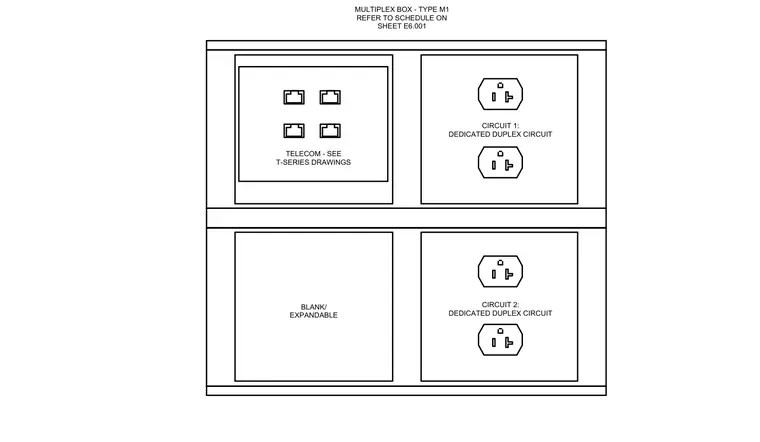
This electrical assembly diagram details a Type M1 multiplex surface box containing four faceplate modules. Circuit 1 supplies two dedicated duplex receptacles in the upper right compartment. Circuit 2 supplies two dedicated duplex receptacles in the lower right compartment. The upper left compartment houses telecom connections coordinated with the T-series drawings, while the lower left compartment remains blank and expandable.
BLANK/ EXPANDABLE CIRCUIT 2: DEDICATED DUPLEX CIRCUIT TELECOM - SEE T-SERIES DRAWINGS MULTIPLEX BOX - TYPE M1 REFER TO SCHEDULE ON SHEET E6.001 CIRCUIT 1: DEDICATED DUPLEX CIRCUIT
Members view this detail in full resolution, download the CAD files (SVG, PDF), and can adapt it in the built-in CAD editor — export DXF, DWG, or PDF.
Start membership