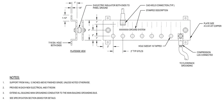
A copper grounding bus plate measuring 4 inches by 1/4 inch by 18 inches features eight 3/8-inch-16 tapped holes spaced typically at 2 inches. The assembly is supported from the wall twelve inches above finished grade unless noted otherwise using brackets with di-electric insulators at both ends. Conductors attach via CAD-weld connections and compression lugs connected to the floor or rack grounding system and panel ground.
NOTES: 1-1/2" PLATESIDE VIEW 1" 1" 4" 2" 2" 1/4" 1" 2" TYP 8 PLCS HOLE SIZE3/8"-16 TAPPED STAMPED DESCRIPTION XXXXXXXX GROUND SYSTEM TO FLOOR/RACK GROUNDING CAD-WELD CONNECTION (TYP.) DI-ELECTRIC INSULATOR BOTH ENDS TO PANEL GROUND COMPRESSION LUG CONNECTED PLATE SIZE 4"x1/4"x18" COPPER 7/16 DIA. HOLE BOTH ENDS 1. SUPPORT FROM WALL 12 INCHES ABOVE FINISHED GRADE, UNLESS NOTED OTHERWISE. 2. PROVIDE IN EACH NEW ELECTRICAL AND IT ROOM. 3. EXTEND ALL BUILDING MAIN GROUNDING CONDUCTOR TO THE MAIN BUILDING GROUNDING BUS. 4. SEE SPECIFICATION SECTION 260452 FOR DETAILS.
Members view this detail in full resolution, download the CAD files (SVG, PDF), and can adapt it in the built-in CAD editor — export DXF, DWG, or PDF.
Start membership