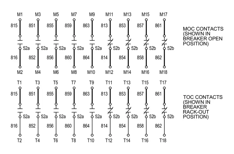
This electrical schematic details the wiring configuration for breaker auxiliary contacts, specifically illustrating Mechanism Operated Cell (MOC) contacts shown in the breaker open position and Truck Operated Cell (TOC) contacts shown in the breaker rack-out position. Numbered terminals M1 through M18 and T1 through T18 correspond to specific contact circuits with designated 52a and 52b auxiliary contact states and associated wire markers.
815 52a 816 851 52a 852 855 52a 856 859 52a 860 863 52a 864 813 52b 814 853 52b 854 857 52b 858 861 52b 862 M2 M4 M6 M8 M10 M12 M14 M16 M18 M1 M3 M5 M7 M9 M11 M13 M15 M17 815 52a 816 851 52a 852 855 52a 856 859 52a 860 863 52a 864 813 52b 814 853 52b 854 857 52b 858 861 52b 862 T2 T4 T6 T8 T10 T12 T14 T16 T18 T1 T3 T5 T7 T9 T11 T13 T15 T17 MOC CONTACTS (SHOWN IN BREAKER OPEN POSITION) TOC CONTACTS (SHOWN IN BREAKER RACK-OUT POSITION)
Members view this detail in full resolution, download the CAD files (SVG, PDF), and can adapt it in the built-in CAD editor — export DXF, DWG, or PDF.
Start membership