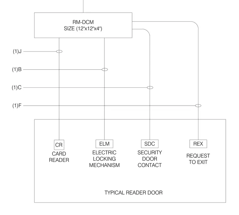
This electrical diagram details the wiring connections for a typical reader door controlled by a room door control module measuring twelve inches by twelve inches by four inches. The control module interfaces with four primary security components including a card reader, an electric locking mechanism, a security door contact, and a request-to-exit device. Specific system wiring paths are designated with annotations (1)J, (1)B, (1)C, and (1)F connecting the respective control points.
RM-DCM SIZE (12"x12"x4") CARD READER ELM ELECTRIC LOCKING MECHANISM SDC SECURITY DOOR CONTACT REQUEST TO EXIT REX TYPICAL READER DOOR (1)J (1)B (1)C (1)F CR
Members view this detail in full resolution, download the CAD files (SVG, PDF), and can adapt it in the built-in CAD editor — export DXF, DWG, or PDF.
Start membership