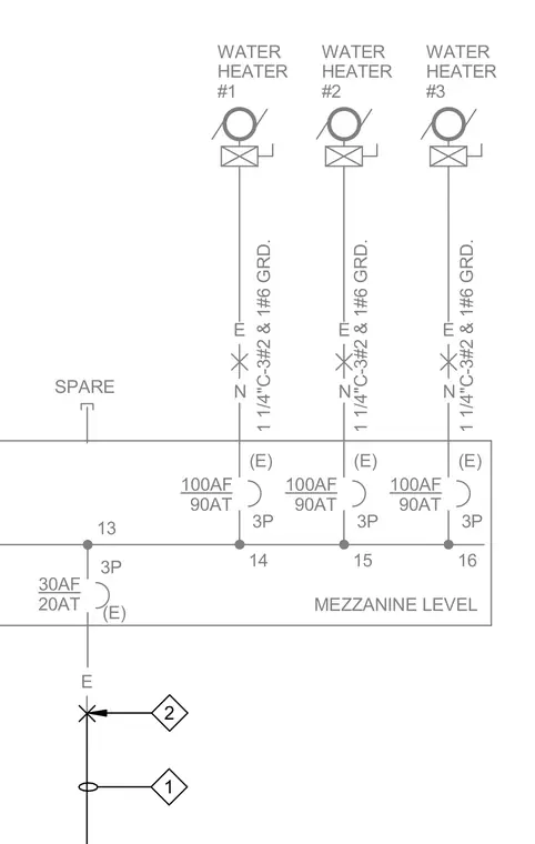
Electrical distribution diagram showing circuit connections for water heaters numbered one through three on the mezzanine level. Each water heater circuit utilizes a one and one-quarter inch conduit enclosing three number two conductors and one number six ground conductor. The diagram includes corresponding circuit breaker ratings of one hundred amp frame and ninety amp trip across three poles with existing conditions noted. A spare circuit with a thirty amp frame and twenty amp trip is also indicated.
WATER HEATER #1 WATER HEATER #2 WATER HEATER #3 1 1/4"C-3#2 & 1#6 GRD. 1 1/4"C-3#2 & 1#6 GRD. 1 1/4"C-3#2 & 1#6 GRD. MEZZANINE LEVEL SPARE E N E N E N 100AF 90AT 3P 14 100AF 90AT 3P 15 100AF 90AT 3P 16 E (E) (E) (E) 20AT 30AF 3P 13 (E) 1 2
Members view this detail in full resolution, download the CAD files (SVG, PDF), and can adapt it in the built-in CAD editor — export DXF, DWG, or PDF.
Start membership