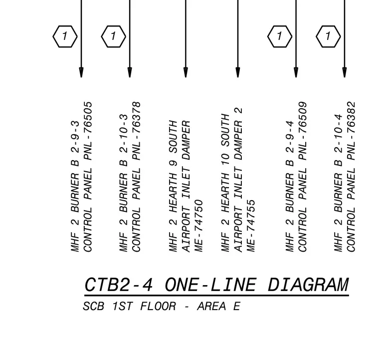
This electrical one-line diagram details control panel and motorized damper connections for the multi-hearth furnace unit on the first floor in area E. Labeled equipment includes burner control panels PNL-76505, PNL-76378, PNL-76509, and PNL-76382 alongside south airport inlet dampers ME-74750 and ME-74755. Feed lines and reference tags coordinate power and signal routing for hearth burners 9 and 10 and burner levels 2-9 and 2-10.
CTB2-4 ONE-LINE DIAGRAM SCB 1ST FLOOR - AREA E MHF 2 BURNER B 2-10-4 CONTROL PANEL PNL-76382 0 MHF 2 BURNER B 2-9-4 CONTROL PANEL PNL-76509 0 MHF 2 HEARTH 10 SOUTH AIRPORT INLET DAMPER 2 ME-74755 MHF 2 HEARTH 9 SOUTH AIRPORT INLET DAMPER ME-74750 MHF 2 BURNER B 2-10-3 CONTROL PANEL PNL-76378 0 MHF 2 BURNER B 2-9-3 CONTROL PANEL PNL-76505 0
Members view this detail in full resolution, download the CAD files (SVG, PDF), and can adapt it in the built-in CAD editor — export DXF, DWG, or PDF.
Start membership