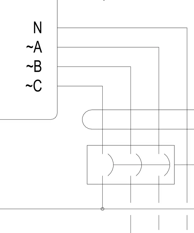
This electrical schematic details the wiring connections for a controls contractor installation, identifying neutral and phases A, B, and C connected to the terminal block. Conductors route through the designated interface terminals per Division 23 specifications.
~C ~B ~A N by Controls Contractor (Div. 23)
Members view this detail in full resolution, download the CAD files (SVG, PDF), and can adapt it in the built-in CAD editor — export DXF, DWG, or PDF.
Start membership