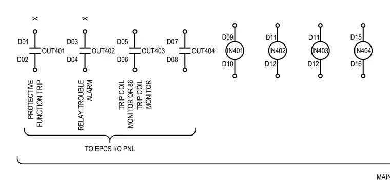
An electrical schematic diagram details output and input relay terminals connected to the EPCS input/output panel. Digital outputs OUT401 through OUT404 link terminals D01 through D08 for protective function trip, relay trouble alarm, and 86 trip coil monitoring functions. Digital inputs IN401 through IN404 connect terminals D09 through D16 across corresponding circuits.
D01 D02 OUT401 D03 D04 OUT402 D05 D06 OUT403 D07 D08 OUT404 IN401 D09 D10 IN402 D11 D12 IN403 D11 D12 IN404 D15 D16 RELAY TROUBLE ALARM X PROTECTIVE FUNCTION TRIP X TO EPCS I/O PNL TRIP COIL MONITOR OR 86 TRIP COIL MONITOR
Members view this detail in full resolution, download the CAD files (SVG, PDF), and can adapt it in the built-in CAD editor — export DXF, DWG, or PDF.
Start membership