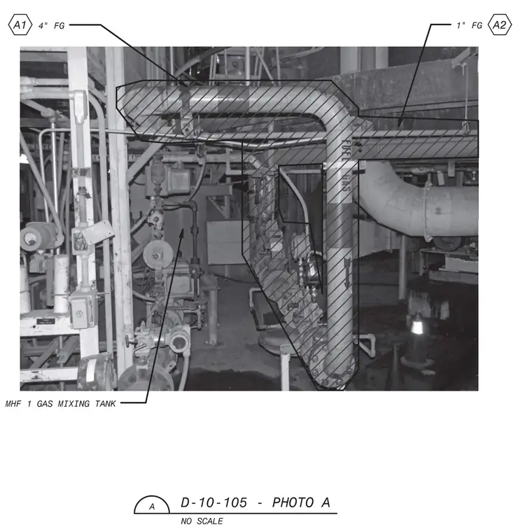
A photograph showing the installation of a four-inch fuel gas line and a one-inch fuel gas line connected to the gas mixing tank D-10-105. The piping features labeled callouts and directional flow markers corresponding to reference bubbles A1 and A2. The industrial room contains associated conduit, valves, and structural supports surrounding the tank equipment.
<£> 1" FG \A2 4" FG 9 V > k H i Oi 1 m % mhd J . -« MHF 1 GAS MIXING TANK D-10-105 - PHOTO A NO SCALE
Members view this detail in full resolution, download the CAD files (SVG, PDF), and can adapt it in the built-in CAD editor — export DXF, DWG, or PDF.
Start membership