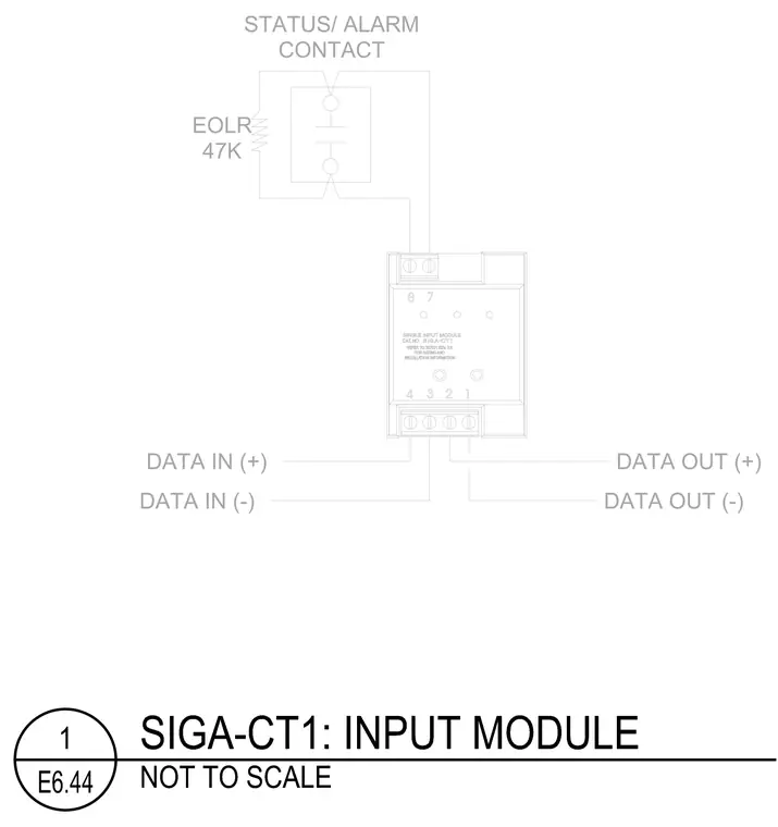
This diagram details the terminal connections for a SIGA-CT1 single input module. Data in and data out lines connect to the lower terminal block with positive and negative polarities. A status or alarm contact ties into the upper terminals, paired with a 47K end-of-line resistor.
Members view this detail in full resolution, download the CAD files (SVG, PDF), and can adapt it in the built-in CAD editor — export DXF, DWG, or PDF.
Start membership