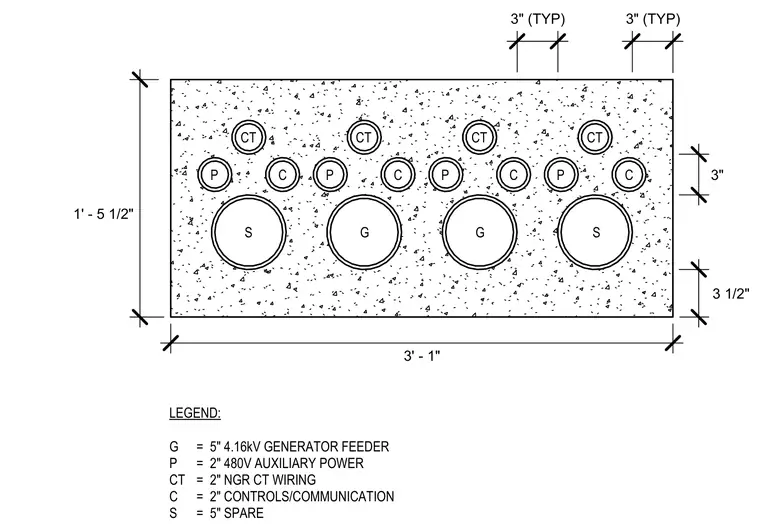
An underground concrete electrical ductbank is arranged with specific conduit sizes and spacings. The assembly measures three feet one inch wide by one foot five and one-half inches high overall. Four five-inch spare and generator feeder conduits, four two-inch auxiliary power conduits, four two-inch controls and communication conduits, and four two-inch NGR CT wiring conduits are encased within the concrete profile. Typical minimum clearances of three inches are maintained between conduits and exterior concrete edges.
3" (TYP) 3' - 1" 1' - 5 1/2" LEGEND: G = 5" 4.16kV GENERATOR FEEDER P = 2" 480V AUXILIARY POWER CT = 2" NGR CT WIRING C = 2" CONTROLS/COMMUNICATION S = 5" SPARE S S P P 3 1/2" 3" G P G P C C C C CT CT CT CT 3" (TYP)
Members view this detail in full resolution, download the CAD files (SVG, PDF), and can adapt it in the built-in CAD editor — export DXF, DWG, or PDF.
Start membership