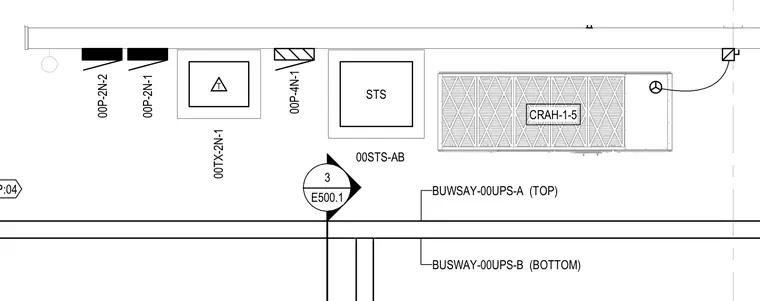
An electrical riser diagram details the routing and connections for top and bottom busway runs alongside associated power distribution units and computer room air handler units. Callouts identify primary busway feeds labeled BUSWAY-00UPS-A and BUSWAY-00UPS-B paired with equipment tags including 00TX-2N-1, STS, and CRAH-1-5. The layout indicates equipment positioning and references drawing E500.1 for related details.
T STS 00TX-2N-1 00P-2N-1 00STS-AB CRAH-1-5 00P-2N-2 00P-4N-1 P:04 BUWSAY-00UPS-A BUSWAY-00UPS-B (TOP) (BOTTOM) E500.1 3 _______
Members view this detail in full resolution, download the CAD files (SVG, PDF), and can adapt it in the built-in CAD editor — export DXF, DWG, or PDF.
Start membership