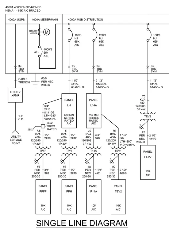
An electrical single line diagram mapping power distribution from the utility service point and transformer through a 4000A main switchboard down to various distribution and branch circuit panels. The utility feed runs via a cable trench with a 4000A meter and main, incorporating a 4/0 grounding electrode conductor sized per NEC 250-66. Feeder conduits and conductors are specified throughout, such as 1.5-inch conduits with 4#1AL and 1#8Cu ground feeding 100/3 series rated panels, and 2.5-inch conduits with 4#250AL and 1#8Cu ground feeding 200/3 panels. Step-down transformers such as 7.5 KVA and 75 KVA units supply 120/208V and 120/240V panels with specific grounding per NEC 250-30 and calculated voltage drops.
SINGLE LINE DIAGRAM UTILITY XFMR POINT SERVICE UTILITY AIC If= SYM 250-66 PER NEC UTILITY METER M 4000/3 65k TBD CABLE TRENCH 1-5" C.O. #3/0 4000A METER/MAIN 4000A UGPS 4000A 480/277v 3P 4W MSB NEMA 1 - 65K AIC BRACED AIC If= SYM 65K TBD 1 1/2" 4#1AL &1#8Cu G HJ 100/3 AIC SERIES RATED PANEL LH 65K MIN KVA PER NEC 250-30 TPH 5 480- 120/240 1P 3W #8 1/2" 2#12 1/2" 3#10 PANEL AIC PPH 10K PANEL AIC PPFP 10K KVA PER NEC 250-30 TPFP 480- 120/240 1P 3W #8 1/2" 2#10 7.5 3/4" 3#8 30/2 SRVC RATED 3/4" 2#10 &1#10G LTH=380' Vd=2.2% #8 AIC If= SYM 65K TBD 2 1/2" 4#250AL &1#8Cu G HJ 200/3 AIC SERIES RATED PANEL L14A 65K MIN PER NEC 250-30 KVA T14A 3#8 3/4" 4#2 1 1/4" 120/208 3P 4W 30 480- #8 PANEL AIC P14A 10K 4000A MSB DISTRIBUTION GFI- AIC If= SYM 65K TBD 1 1/2" 4#1AL &1#8Cu G HJ 100/3 KVA PER NEC 250-30 TEV2 75 480- 120/208 3P 4W #2 2 1/2" 4#4/0 PANEL AIC PEV2 10K KVA PER NEC 250-30 TEV1 75 480- 120/208 3P 4W #2 1 1/4" 3#2 2 1/2" 4#4/0 PANEL AIC TEV2 10K LTH=200' V.D.=0.93%
Members view this detail in full resolution, download the CAD files (SVG, PDF), and can adapt it in the built-in CAD editor — export DXF, DWG, or PDF.
Start membership