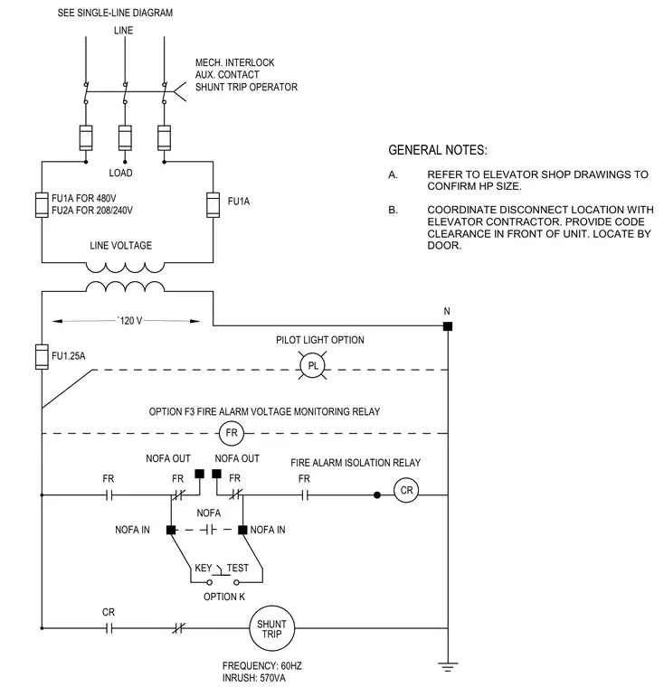
An electrical schematic for an elevator disconnect shows line voltage entering through fuses, a transformer stepping down to one hundred twenty volts, and a shunt trip operator tied to auxiliary contacts and a mechanical interlock. Fuses protect the line and load sides with specific ratings for four hundred eighty or two hundred eight to two hundred forty volt configurations. Optional components include a pilot light, a fire alarm voltage monitoring relay, and a key test switch. General notes require coordination with elevator shop drawings for horsepower size and proper disconnect placement near the door with required code clearances.
SEE SINGLE-LINE DIAGRAM MECH. INTERLOCK AUX. CONTACT SHUNT TRIP OPERATOR A. REFER TO ELEVATOR SHOP DRAWINGS TO CONFIRM HP SIZE. B. COORDINATE DISCONNECT LOCATION WITH ELEVATOR CONTRACTOR. PROVIDE CODE CLEARANCE IN FRONT OF UNIT. LOCATE BY DOOR. LINE VOLTAGE FU1A FU1A FOR 480V FU2A FOR 208/240V `120 V LINE LOAD FU1.25A PL FR PILOT LIGHT OPTION OPTION F3 FIRE ALARM VOLTAGE MONITORING RELAY N FR FR FR FR NOFA OUT NOFA OUT CR NOFA IN NOFA IN NOFA OPTION K KEY TEST CR TRIP SHUNT FIRE ALARM ISOLATION RELAY FREQUENCY: 60HZ INRUSH: 570VA GENERAL NOTES:
Members view this detail in full resolution, download the CAD files (SVG, PDF), and can adapt it in the built-in CAD editor — export DXF, DWG, or PDF.
Start membership