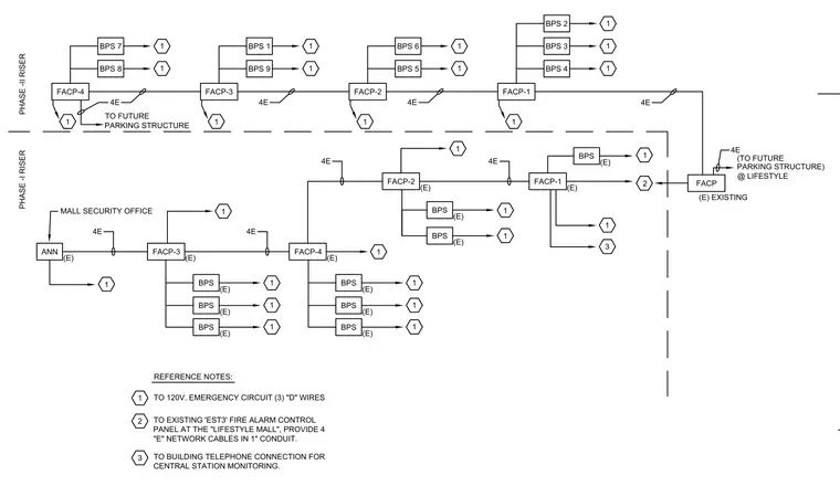
Fire alarm system riser diagram mapping the connections between multiple fire alarm control panels, booster power supplies, and annunciators across Phase I and Phase II construction. Network cables run in 1-inch conduit to the existing EST3 fire alarm control panel at the lifestyle mall. Reference notes specify requirements for 120-volt emergency circuits with three D wires, building telephone connections for central station monitoring, and network cabling. The layout includes interconnections to future parking structures and the mall security office.
1 2 3 REFERENCE NOTES: TO EXISTING 'EST3' FIRE ALARM CONTROL PANEL AT THE "LIFESTYLE MALL", PROVIDE 4 "E" NETWORK CABLES IN 1" CONDUIT. TO BUILDING TELEPHONE CONNECTION FOR CENTRAL STATION MONITORING. TO 120V. EMERGENCY CIRCUIT (3) "D" WIRES FACP-1 1 BPS 2 1 3 FACP-2 BPS BPS 4E 1 1 ANN FACP-4 BPS BPS 1 1 BPS 1 1 MALL SECURITY OFFICE FACP-3 BPS BPS 1 1 BPS 1 4E 4E 1 4E 1 1 PHASE -I RISER (E) (E) (E) (E) (E) (E) (E) (E) (E) (E) (E) (E) (E) (E) PHASE -II RISER FACP-4 BPS 7 BPS 8 TO FUTURE PARKING STRUCTURE 1 FACP-3 BPS 1 BPS 9 1 1 1 1 1 4E FACP-2 BPS 6 BPS 5 1 1 1 4E FACP-1 BPS 3 BPS 4 1 1 1 4E BPS 2 1 4E FACP (E) EXISTING 4E PARKING STRUCTURE) @ LIFESTYLE (TO FUTURE
Members view this detail in full resolution, download the CAD files (SVG, PDF), and can adapt it in the built-in CAD editor — export DXF, DWG, or PDF.
Start membership