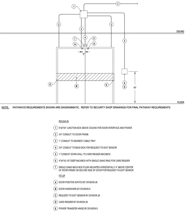
Security rough-in and conduit pathways for a door access control system extend from a six-by-six-by-four-inch junction box located above the ceiling. A one-inch conduit runs to the nearest cable tray, while three-quarter-inch conduits feed down to the door frame and the request-to-exit sensor backbox. A one-inch conduit extends down the wall to a four-by-four-by-two-and-one-eighth-inch deep backbox with a single gang ring serving the card reader at forty-eight inches above the floor. Interface coordination is required with Division eight for door hardware and power transfer hinges, and Division twenty-eight for door position switches, request-to-exit sensors, and card readers.
6" 1 2 3 4 A B C 3 2 A B 1 A 4 C 6"x6"X4" JUNCTION BOX ABOVE CEILING FOR DOOR INTERFACE AND POWER 3/4" CONDUIT TO DOOR FRAME 1" CONDUIT TO NEAREST CABLE TRAY 3/4" CONDUIT TO BACK BOX FOR REQUEST-TO-EXIT SENSOR ROUGH-IN FIT-UP DOOR HARDWARE BY DIVISION 8 DOOR POSITION SWITCH BY DIVISION 28 REQUEST-TO-EXIT SENSOR BY DIVISION 28 2 2 5 6 D E E 5 1" CONDUIT DOWN WALL TO CARD READER BACKBOX 6 4"X4"X2-1/8" DEEP BACKBOX WITH SINGLE GANG RING FOR CARD READER D CARD READER BY DIVISION 28 E POWER TRANSFER HINGE BY DIVISION 8 7 SINGLE GANG BACK BOX FLUSH MOUNTED HORIZONTALLY 4" ABOVE CENTER OF DOOR FRAME ON SECURE SIDE OF DOOR FOR REQUEST-TO-EXIT SENSOR 48" 7 CEILING FLOOR NOTE: PATHWAYS REQUIREMENTS SHOWN ARE DIAGRAMMATIC. REFER TO SECURITY SHOP DRAWINGS FOR FINAL PATHWAY REQUIREMENTS CEILING FLOOR NOTE: PATHWAYS REQUIREMENTS SHOWN ARE DIAGRAMMATIC. REFER TO SECURITY SHOP DRAWINGS FOR FINAL PATHWAY REQUIREMENTS
Members view this detail in full resolution, download the CAD files (SVG, PDF), and can adapt it in the built-in CAD editor — export DXF, DWG, or PDF.
Start membership