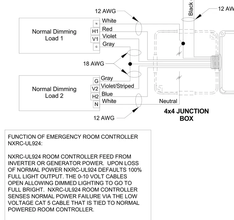
An emergency room controller receives feed from an inverter or generator power source to maintain functionality during outages. Upon a loss of normal power, the controller defaults to one hundred percent full light output while zero to ten volt cables open to allow dimmed lighting to reach full brightness. The controller senses normal power failure through a low voltage cat five cable tied to the normally powered room controller. Connections utilize twelve American Wire Gauge conductors for line and neutral feeds alongside eighteen American Wire Gauge wires for dimming loads.
4x4 JUNCTION BOX FUNCTION OF EMERGENCY ROOM CONTROLLER NXRC-UL924: NXRC-UL924 ROOM CONTROLLER FEED FROM INVERTER OR GENERATOR POWER. UPON LOSS OF NORMAL POWER NXRC-UL924 DEFAULTS 100% FULL LIGHT OUTPUT. THE 0-10 VOLT CABLES OPEN ALLOWING DIMMED LIGHTING TO GO TO FULL BRIGHT. NXRC-UL924 ROOM CONTROLLER SENSES NORMAL POWER FAILURE VIA THE LOW VOLTAGE CAT 5 CABLE THAT IS TIED TO NORMAL POWERED ROOM CONTROLLER. 12 AWG 18 AWG 12 AWG 12 AWG Black (Line 120/277/347 VAC) G V1 H1 N N H2 V2 G Normal Dimming Load 1 Normal Dimming Load 2 Violet Gray Red White Gray White Blue Violet/Striped Neutral
Members view this detail in full resolution, download the CAD files (SVG, PDF), and can adapt it in the built-in CAD editor — export DXF, DWG, or PDF.
Start membership