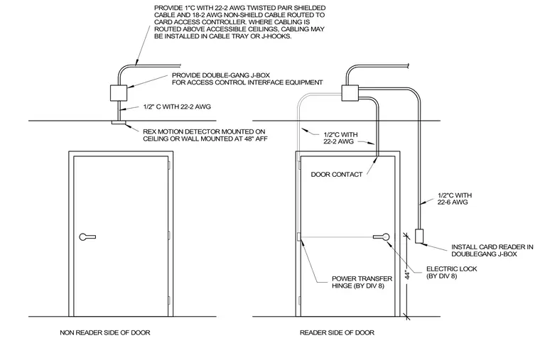
Card access control wiring is routed through conduits to interface equipment above the ceiling. A one-inch conduit contains a twenty-two gauge two-conductor twisted pair shielded cable and an eighteen-gauge two-conductor non-shielded cable routed to the card access controller, with cabling installed in cable trays or J-hooks above accessible ceilings. A double-gang junction box houses interface equipment, connecting via half-inch conduit and twenty-two gauge two-conductor cabling to a request-to-exit motion detector mounted on the ceiling or wall at forty-eight inches above finished floor on the non-reader side. The reader side features a half-inch conduit with twenty-two gauge two-conductor cabling to a door contact, a half-inch conduit with twenty-two gauge six-conductor cabling to a card reader installed in a double-gang junction box at forty-four inches above finished floor, and low-voltage connections through a power transfer hinge and electric lock provided by Division 8.
PROVIDE 1"C WITH 22-2 AWG TWISTED PAIR SHIELDED CABLE AND 18-2 AWG NON-SHIELD CABLE ROUTED TO CARD ACCESS CONTROLLER. WHERE CABLING IS ROUTED ABOVE ACCESSIBLE CEILINGS, CABLING MAY BE INSTALLED IN CABLE TRAY OR J-HOOKS. PROVIDE DOUBLE-GANG J-BOX FOR ACCESS CONTROL INTERFACE EQUIPMENT 1/2" C WITH 22-2 AWG REX MOTION DETECTOR MOUNTED ON CEILING OR WALL MOUNTED AT 48" AFF NON READER SIDE OF DOOR 1/2"C WITH 22-2 AWG DOOR CONTACT 1/2"C WITH 22-6 AWG INSTALL CARD READER IN DOUBLEGANG J-BOX 44" READER SIDE OF DOOR POWER TRANSFER HINGE (BY DIV 8) ELECTRIC LOCK (BY DIV 8)
Members view this detail in full resolution, download the CAD files (SVG, PDF), and can adapt it in the built-in CAD editor — export DXF, DWG, or PDF.
Start membership