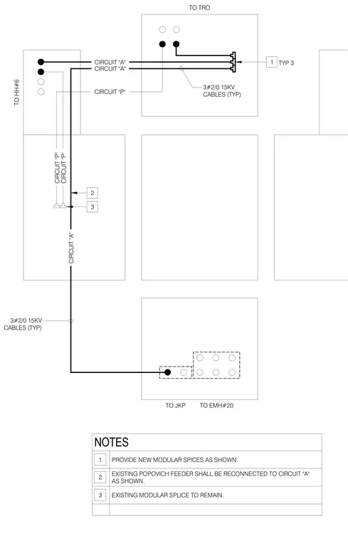
This diagram details electrical cabling inside a manhole, routing three two-slash-zero fifteen kilovolt cables typically for circuit "A" and circuit "P". New modular splices are provided as indicated by callout one. The existing Popovich feeder reconnects to circuit "A" per note two, while the existing modular splice remains in place per note three. Cabling connects between handhole number six, transformer, electrical manhole number twenty, and junction point.
TO TRO TO EMH#20 TO HH#6 TO JKP CIRCUIT "A" CIRCUIT "P" CIRCUIT "A" CIRCUIT "P" CIRCUIT "P" CIRCUIT "A" 3#2/0 15KV CABLES (TYP) 2 3#2/0 15KV CABLES (TYP) 1 3 TYP 3 NOTES PROVIDE NEW MODULAR SPICES AS SHOWN. EXISTING POPOVICH FEEDER SHALL BE RECONNECTED TO CIRCUIT "A" AS SHOWN. EXISTING MODULAR SPLICE TO REMAIN. 1 2 3
Members view this detail in full resolution, download the CAD files (SVG, PDF), and can adapt it in the built-in CAD editor — export DXF, DWG, or PDF.
Start membership