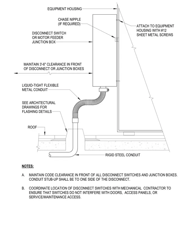
An exterior electrical disconnect switch or motor feeder junction box mounts directly to the equipment housing using number twelve sheet metal screws. A chase nipple connects the box where required, and a liquid-tight flexible metal conduit transitions to a rigid steel conduit stubbing up through the roof slab. A three-foot-six-inch clearance is maintained in front of all disconnect switches and junction boxes per code requirements. Flashing details at the roof penetration are coordinated with architectural drawings.
EQUIPMENT HOUSING CHASE NIPPLE (IF REQUIRED) DISCONNECT SWITCH OR MOTOR FEEDER JUNCTION BOX MAINTAIN 3'-6" CLEARANCE IN FRONT OF DISCONNECT OR JUNCTION BOXES LIQUID-TIGHT FLEXIBLE METAL CONDUIT SEE ARCHITECTURAL DRAWINGS FOR FLASHING DETAILS ROOF RIGID STEEL CONDUIT NOTES: A. MAINTAIN CODE CLEARANCE IN FRONT OF ALL DISCONNECT SWITCHES AND JUNCTION BOXES. CONDUIT STUB-UP SHALL BE TO ONE SIDE OF THE DISCONNECT. B. COORDINATE LOCATION OF DISCONNECT SWITCHES WITH MECHANICAL CONTRACTOR TO ENSURE THAT SWITCHES DO NOT INTERFERE WITH DOORS, ACCESS PANELS, OR SERVICE/MAINTENANCE ACCESS. ATTACH TO EQUIPMENT HOUSING WITH #12 SHEET METAL SCREWS
Members view this detail in full resolution, download the CAD files (SVG, PDF), and can adapt it in the built-in CAD editor — export DXF, DWG, or PDF.
Start membership