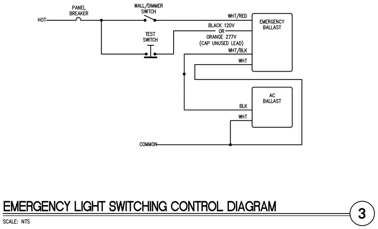
An emergency lighting control circuit connects a panel breaker to an emergency ballast and an AC ballast through a wall or dimmer switch. A hot wire feeds through a panel breaker to the wall switch and branches to a test switch, which connects to the emergency ballast. The emergency ballast accepts a black lead for one hundred twenty volts or an orange lead for two hundred seventy volts, with unused leads capped, and is wired using white, red, and black conductors. The AC ballast connects in parallel for standard lighting operation while sharing a common neutral return.
Members view this detail in full resolution, download the CAD files (SVG, PDF), and can adapt it in the built-in CAD editor — export DXF, DWG, or PDF.
Start membership