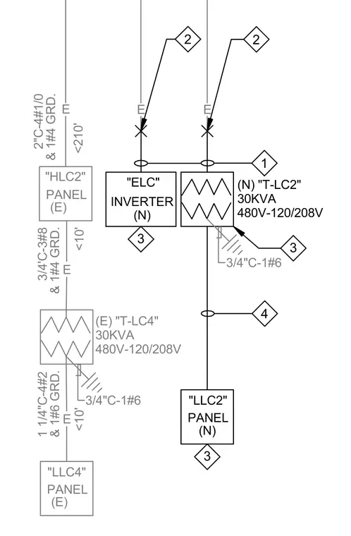
This electrical riser diagram maps the connections between a new inverter ELC and associated transformers and panels. The system incorporates new 30 kVA 480V to 120/208V transformers T-LC2 and T-LC4 alongside existing panels HLC2 and LLC4 and new panel LLC2. Conduit and wire sizing are specified for each run, including 2-inch conduit with four 1/0 conductors and one number 4 ground for the 210-foot run to panel HLC2, and 3/4-inch conduit with three number 8 conductors and one number 4 ground for the 10-foot run. Additional connections utilize 1 1/4-inch conduit with four number 2 conductors and one number 6 ground for existing panel LLC4.
(N) PANEL "LLC2" (N) INVERTER "ELC" (N) "T-LC2" 30KVA 480V-120/208V (E) PANEL "HLC2" <210' & 1#4 GRD. 2"C-4#1/0 <10' & 1#4 GRD. 3/4'C-3#8 (E) PANEL "LLC4" <10' & 1#6 GRD. 1 1/4"C-4#2 E E E E E 3/4"C-1#6 3/4"C-1#6 (E) "T-LC4" 30KVA 480V-120/208V 3 3 3 2 4 2 1
Members view this detail in full resolution, download the CAD files (SVG, PDF), and can adapt it in the built-in CAD editor — export DXF, DWG, or PDF.
Start membership