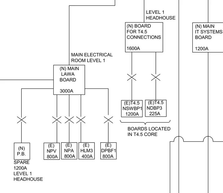
The schematic outlines the main electrical room level one distribution network originating from a 3000A main LAWA board. Power feeds descend to a 1200A spare panelboard, an 800A NPV board, an 800A NPA board, a 400A HLM3 board, and an 800A DPBF1 board. Additional lines extend to a 1600A board for T4.5 connections in the level 1 headhouse, feeding existing 1200A NSWBP1 and 225A NDBP3 boards located in the T4.5 core. A separate 1200A main IT systems board is also integrated into the layout.
(N) MAIN LAWA BOARD 3000A MAIN ELECTRICAL ROOM LEVEL 1 (N) P.B. SPARE 1200A LEVEL 1 HEADHOUSE (E) NPV 800A (E) NPA 800A (E) HLM3 400A (E) DPBF1 800A (N) BOARD FOR T4.5 CONNECTIONS 1600A LEVEL 1 HEADHOUSE (E)T4.5 NSWBP1 1200A (E)T4.5 NDBP3 225A BOARDS LOCATED IN T4.5 CORE (N) MAIN IT SYSTEMS BOARD 1200A
Members view this detail in full resolution, download the CAD files (SVG, PDF), and can adapt it in the built-in CAD editor — export DXF, DWG, or PDF.
Start membership