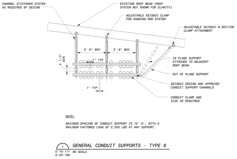
A trapeze-style conduit support assembly is suspended from an existing roof beam using adjustable seismic clamps and hanging rods. In-plane and out-of-plane seismic supports consisting of adjustable W-section clamp attachments and diagonal bracing are tied to adjacent structural members. Horizontal seismic design and approved conduit support channels carry the runs of conduits secured with appropriately sized conduit clamps spaced at a maximum of ten feet on center. A channel stiffener system is included as required by design, maintaining a maximum spacing of three feet six inches between vertical hangers. The system is designed to accommodate a maximum factored load of 2,500 pounds at any support.
EXISTING ROOF BEAM (ROOF SYSTEM NOT SHOWN FOR CLARITY) CHANNEL STIFFENER SYSTEM AS REQUIRED BY DESIGN — ADJUSTABLE SEISMIC CLAMP FOR HANGING ROD SYSTEM ADJUSTABLE SEISMIC W-SECTION CLAMP ATTACHMENT 7/ > 3' -6" MAX 3‘ -6" MAX / CM IN PLANE SUPPORT ATTACHED TO ADJACENT ROOF BEAM 1" TYP *1— IV 'I -'I 3 I hy/ + OUT OF PLANE SUPPORT SEISMIC DESIGN AND APPROVED CONDUIT SUPPORT CHANNELS 1" TYP CONDUIT CLAMP AND SIZE AS REQUIRED NOTE: MAXIMUM SPACING OF CONDUIT SUPPORT IS 10' -0", WITH A MAXIMUM FACTORED LOAD OF 2,500 LBS AT ANY SUPPORT. yT\ GENERAL CONDUIT SUPPORTS - TYPE 8 E-10-111 NO SCALE E-40-108
Members view this detail in full resolution, download the CAD files (SVG, PDF), and can adapt it in the built-in CAD editor — export DXF, DWG, or PDF.
Start membership