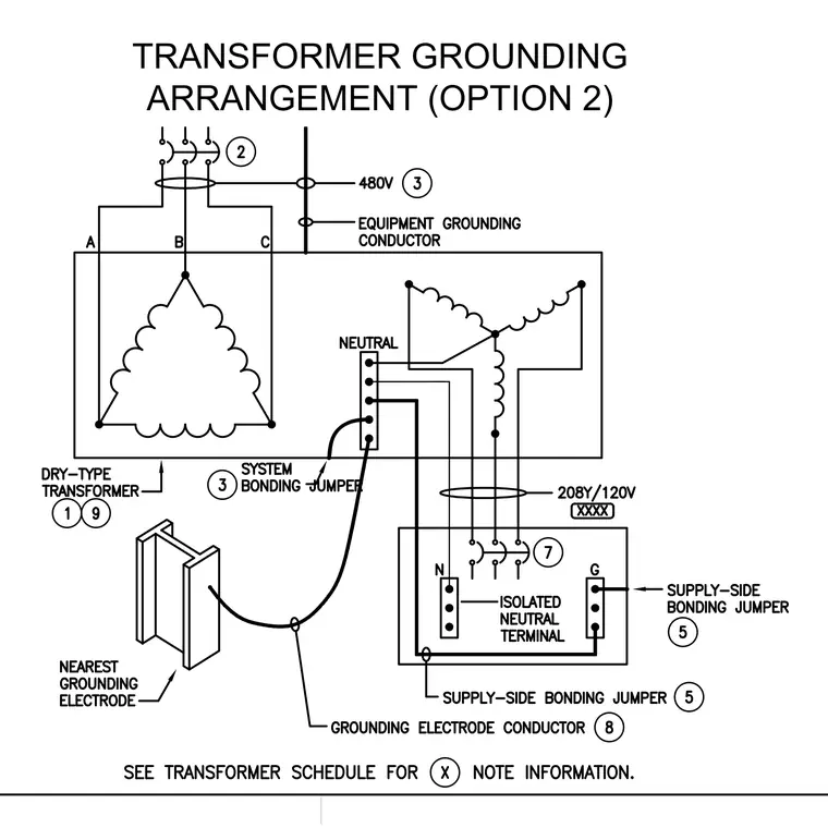
This diagram details the grounding configuration for a dry-type transformer featuring a 480V primary supply and a 208Y/120V secondary distribution. A system bonding jumper connects the neutral bar to the transformer enclosure, while a grounding electrode conductor runs from the neutral bar to the nearest grounding electrode. An equipment grounding conductor accompanies the primary feeder. On the secondary side, an isolated neutral terminal and supply-side bonding jumpers maintain proper grounding continuity.
Members view this detail in full resolution, download the CAD files (SVG, PDF), and can adapt it in the built-in CAD editor — export DXF, DWG, or PDF.
Start membership