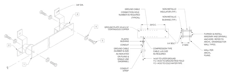
A continuous copper ground plate measuring twenty-four by four by one-quarter inches is mounted to a masonry or drywall wall using non-metallic insulators and non-metallic bushings spaced at twenty inches on center with one-quarter-inch bolts. The assembly uses masonry and drywall anchors sized per architectural plans with a maximum three-inch projection. A ground cable connects to the plate via a compression-type cable lug and conduit secured with a conduit strap. The conduit contains a one-zero wire size three-slash-zero cable routed to the Ufer ground, ground rod field, or cold water pipe as indicated on single line diagrams.
3/8" DIA. CL 5 4 3 2 1 PLASTIC 1"C-1#3/0 TO COLD WATER PIPE. 1#3/0 TO UFER GROUND DIAGRAMS.) SINGLE LINE BUSHING CONDUIT GROUND CABLE (NUMBER & SIZE AS INDICATED ON PLANS & CONDUIT STRAP COMPRESSION TYPE CABLE LUG SIZE AS REQUIRED. 1/4" BOLT WALL PER ARCH'L. PLANS. 3" MAX FURNISH & INSTALL MASONRY AND DRYWALL ANCHORS. REFER TO ARCH'L. DRAWINGS FOR WALL TYPES. INSULATOR (TYP.) BUSHING (TYP.) NON-METALLIC NON-METALLIC CONTINUOUS COPPER (TYPICAL) GROUND PLATE 24"x4"x1/4" GROUND CABLE CONNECTION HOLE. NUMBER AS REQUIRED 20"O.C. 1"C-1#3/0 TO GROUND ROD FEILD
Members view this detail in full resolution, download the CAD files (SVG, PDF), and can adapt it in the built-in CAD editor — export DXF, DWG, or PDF.
Start membership