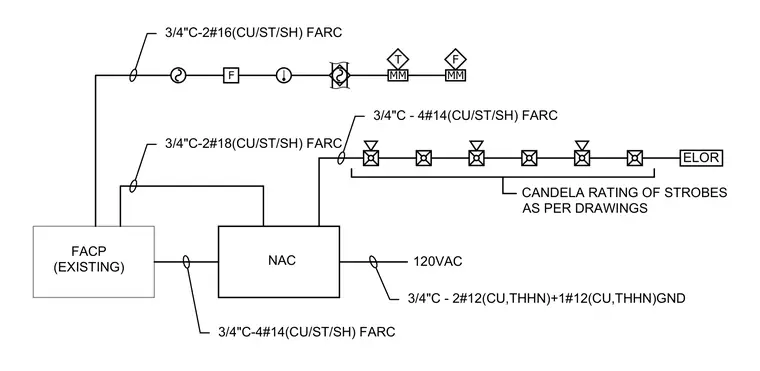
This electrical riser diagram outlines the fire alarm wiring connections originating from an existing fire alarm control panel connected to a notification appliance circuit panel. The system distributes power via three-quarter-inch conduit containing copper THHN conductors with a ground for one-hundred-twenty-volt alternating current. Signal line circuits utilize three-quarter-inch conduit with shielded copper twisted pair fire alarm cables routed to various notification appliances and modules. Strobe candela ratings are designated to be installed as per drawings with dedicated notification circuits.
T F MM F MM 3/4"C - 4#14(CU/ST/SH) FARC 3/4"C-2#16(CU/ST/SH) FARC CANDELA RATING OF STROBES AS PER DRAWINGS 3/4"C-4#14(CU/ST/SH) FARC 3/4"C-2#18(CU/ST/SH) FARC 120VAC 3/4"C - 2#12(CU,THHN)+1#12(CU,THHN)GND FACP (EXISTING) NAC ELOR
Members view this detail in full resolution, download the CAD files (SVG, PDF), and can adapt it in the built-in CAD editor — export DXF, DWG, or PDF.
Start membership