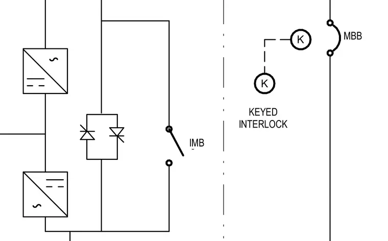
An electrical schematic diagram details a circuit configuration incorporating power conversion blocks, solid-state switching elements, and a bypass switch designated as IMB. A mechanical or electrical linkage system provides safety control through a keyed interlock indicated by symbol K. Main breaker contacts labeled MBB complete the switching logic across the circuit lines.
Members view this detail in full resolution, download the CAD files (SVG, PDF), and can adapt it in the built-in CAD editor — export DXF, DWG, or PDF.
Start membership