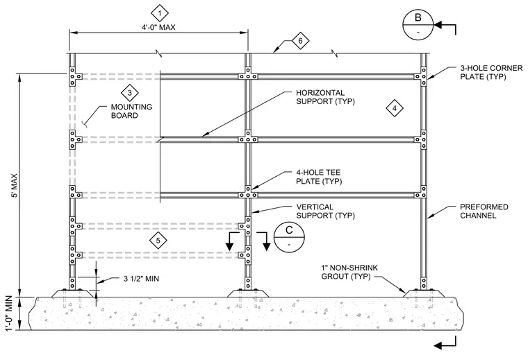
Vertical supports and horizontal supports are connected using preformed channel members, secured with 3-hole corner plates and 4-hole tee plates typically throughout the assembly. The base of each vertical support rests on a concrete foundation with a minimum 1-inch thick non-shrink grout layer. Mounting boards are attached to the framing layout with maximum spacing dimensions of 4 feet horizontally and 5 feet vertically. Clearances include a minimum 3 and 1/2 inch dimension above the grout pad and a minimum 1 foot depth for the concrete element.
4 PREFORMED CHANNEL 3-HOLE CORNER PLATE (TYP) 4-HOLE TEE PLATE (TYP) 1" NON-SHRINK GROUT (TYP) VERTICAL SUPPORT (TYP) HORIZONTAL SUPPORT (TYP) C - B - 3 1/2" MIN 3 MOUNTING BOARD 1 5 1'-0" MIN 5' MAX 4'-0" MAX 6
Members view this detail in full resolution, download the CAD files (SVG, PDF), and can adapt it in the built-in CAD editor — export DXF, DWG, or PDF.
Start membership