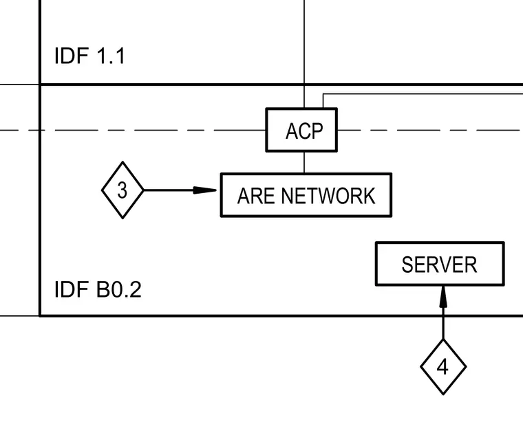
Network diagram illustrating the connection layout for the ARE network linking intermediate distribution frames IDF 1.1 and IDF B0.2 with an ACP unit and server equipment. Lines route the communication pathway between the designated nodes.
Members view this detail in full resolution, download the CAD files (SVG, PDF), and can adapt it in the built-in CAD editor — export DXF, DWG, or PDF.
Start membership