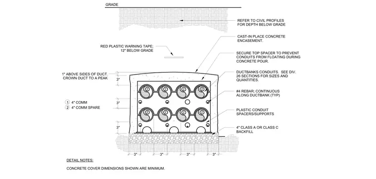
An underground electrical ductbank assembly comprises a cast-in-place concrete encasement crowned to a peak with a one-inch clearance above the sides of the conduits. The interior houses an eight-conduit arrangement of four-inch communication lines and four-inch spare communication lines supported by plastic conduit spacers. Continuous number four reinforcing bars run longitudinally along the ductbank corners and interior. The concrete encasement provides a minimum of three inches of cover around the conduits and rests on a four-inch layer of class A or class C backfill. Red plastic warning tape is positioned twelve inches below grade and twelve inches above the top of the encasement.
3" 3" 3" 1" ABOVE SIDES OF DUCT. CROWN DUCT TO A PEAK CAST-IN PLACE CONCRETE ENCASEMENT. SECURE TOP SPACER TO PREVENT CONDUITS FROM FLOATING DURING CONCRETE POUR. DUCTBANKS CONDUITS. SEE DIV. 26 SECTIONS FOR SIZES AND QUANTITIES. #4 REBAR; CONTINUOUS ALONG DUCTBANK (TYP) 4" CLASS A OR CLASS C BACKFILL PLASTIC CONDUIT SPACERS/SUPPORTS DETAIL NOTES: CONCRETE COVER DIMENSIONS SHOWN ARE MINIMUM. RED PLASTIC WARNING TAPE; 12" BELOW GRADE 3" 3" 3" 1 4" COMM 2 4" COMM SPARE GRADE REFER TO CIVIL PROFILES FOR DEPTH BELOW GRADE 2 2 2 2 2 2 2 2 3"
Members view this detail in full resolution, download the CAD files (SVG, PDF), and can adapt it in the built-in CAD editor — export DXF, DWG, or PDF.
Start membership