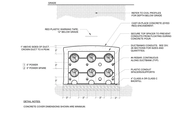
An underground electrical ductbank features a red-dyed cast-in-place concrete encasement crowned to a peak with one inch of cover above the sides. Six five-inch power and spare conduits are arranged in a three-by-two configuration, supported by plastic conduit spacers and secured at the top to prevent floating during the concrete pour. Continuous number four reinforcing bars run longitudinally along the ductbank with minimum concrete cover dimensions as specified. The encasement rests on four inches of Class A or Class C backfill material. Red plastic warning tape is positioned twelve inches below the finish grade, and overall depth below grade is referenced from civil profiles.
3" 3" 3" 1" ABOVE SIDES OF DUCT. CROWN DUCT TO A PEAK CAST-IN PLACE CONCRETE (DYED RED) ENCASEMENT. SECURE TOP SPACER TO PREVENT CONDUITS FROM FLOATING DURING CONCRETE POUR. DUCTBANKS CONDUITS. SEE DIV. 26 SECTIONS FOR SIZES AND QUANTITIES. #4 REBAR; CONTINUOUS ALONG DUCTBANK (TYP) 4" CLASS A OR CLASS C BACKFILL PLASTIC CONDUIT SPACERS/SUPPORTS DETAIL NOTES: CONCRETE COVER DIMENSIONS SHOWN ARE MINIMUM. RED PLASTIC WARNING TAPE; 12" BELOW GRADE 3" 3" 2 2 2 2 2 2 3" 1 5" POWER 2 5" POWER SPARE GRADE REFER TO CIVIL PROFILES FOR DEPTH BELOW GRADE 3"
Members view this detail in full resolution, download the CAD files (SVG, PDF), and can adapt it in the built-in CAD editor — export DXF, DWG, or PDF.
Start membership