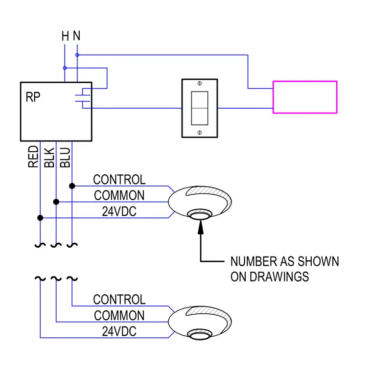
An electrical schematic detailing control wiring connections from a relay panel labeled RP utilizing red, black, and blue conductors. The circuit integrates hot and neutral supply lines feeding into a switch device with a faceplate and a connected load. Low voltage sensors or control devices interface with control, common, and 24VDC lines configured as indicated on the drawings.
H N RP RED BLK BLU CONTROL COMMON 24VDC CONTROL COMMON 24VDC NUMBER AS SHOWN ON DRAWINGS
Members view this detail in full resolution, download the CAD files (SVG, PDF), and can adapt it in the built-in CAD editor — export DXF, DWG, or PDF.
Start membership