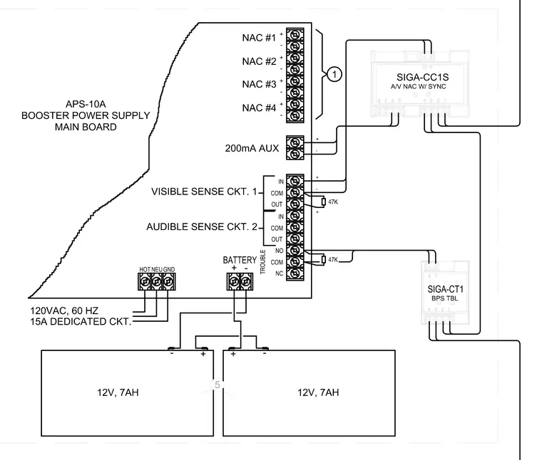
This electrical wiring diagram details the connections between an APS-10A booster power supply main board and associated fire alarm control modules. The main board is powered by a dedicated 120-volt alternating current, sixty hertz, fifteen-ampere circuit connected to the hot, neutral, and ground terminals. Two twelve-volt, seven-ampere-hour backup batteries connect in series to the battery terminals for emergency power. The SIGA-CC1S audio-visual notification appliance circuit control module interfaces with the notification appliance circuits numbered one through four, a two-hundred-milliampere auxiliary output, and visible and audible sense circuits equipped with forty-seven-kilohm end-of-line resistors. A SIGA-CT1 monitor module connects to the trouble contacts of the power supply main board.
Members view this detail in full resolution, download the CAD files (SVG, PDF), and can adapt it in the built-in CAD editor — export DXF, DWG, or PDF.
Start membership