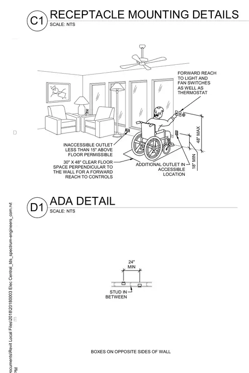
Electrical receptacles and control switches are mounted within accessible reach ranges, maintaining an eighteen-inch minimum and forty-eight-inch maximum height above the finished floor. A thirty-inch by forty-eight-inch clear floor space is provided perpendicular to the wall for forward reach to controls. Outlets mounted on opposite sides of the wall maintain a twenty-four-inch minimum separation between wall studs.
BOXES ON OPPOSITE SIDES OF WALL STUD IN BETWEEN 24" MIN INACCESSIBLE OUTLET LESS THAN 15" ABOVE FLOOR PERMISSIBLE 30" X 48" CLEAR FLOOR SPACE PERPENDICULAR TO THE WALL FOR A FORWARD REACH TO CONTROLS ADDITIONAL OUTLET IN ACCESSIBLE LOCATION FORWARD REACH TO LIGHT AND FAN SWITCHES AS WELL AS THERMOSTAT 48" MAX 18" MIN E D SCALE: NTS ADA DETAIL D1 SCALE: NTS C1 RECEPTACLE MOUNTING DETAILS
Members view this detail in full resolution, download the CAD files (SVG, PDF), and can adapt it in the built-in CAD editor — export DXF, DWG, or PDF.
Start membership