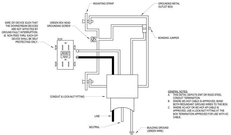
Wiring configuration for a GFI receptacle wired so that downstream devices are not affected by ground fault interruption. The GFI device is connected via line and neutral wires while utilizing a mounting strap secured to a grounded metal outlet box. A green hex head grounding screw establishes continuity with a bonding jumper and a building ground wire. A conduit and lock-nut fitting terminates the incoming circuit at the outlet box. General notes specify requirements for EMT, rigid steel, and MC-HCF cable terminations.
WIRE GFI DEVICE SUCH THAT THE DOWNSTREAM DEVICES ARE NOT AFFECTED BY GROUND FAULT INTERRUPTION. IE. NON FEED THRU. EACH GFI DEVICE SHALL BE SELF PROTECTING ONLY. RESET TEST MOUNTING STRAP GROUNDED METAL OUTLET BOX BONDING JUMPER BUILDING GROUND (GREEN WIRE) CONDUIT & LOCK-NUT FITTING GREEN HEX HEAD GROUNDING SCREW NEUTRAL LINE GENERAL NOTES: A. THIS DETAIL DEPICTS EMT OR RIGID STEEL CONDUIT TERMINATION. B. WHERE MC-HCF CABLE IS APPROVED, BOND BOTH REDUNDANT GROUND WIRES TO THE BOX. C. WHERE AC-HCF OR MC-HCF-AP CABLE IS APPROVED, USE A LOCK-NUT FITTING AT THE BOX TERMINATION APPROVED FOR USE WITH AC CABLE.
Members view this detail in full resolution, download the CAD files (SVG, PDF), and can adapt it in the built-in CAD editor — export DXF, DWG, or PDF.
Start membership