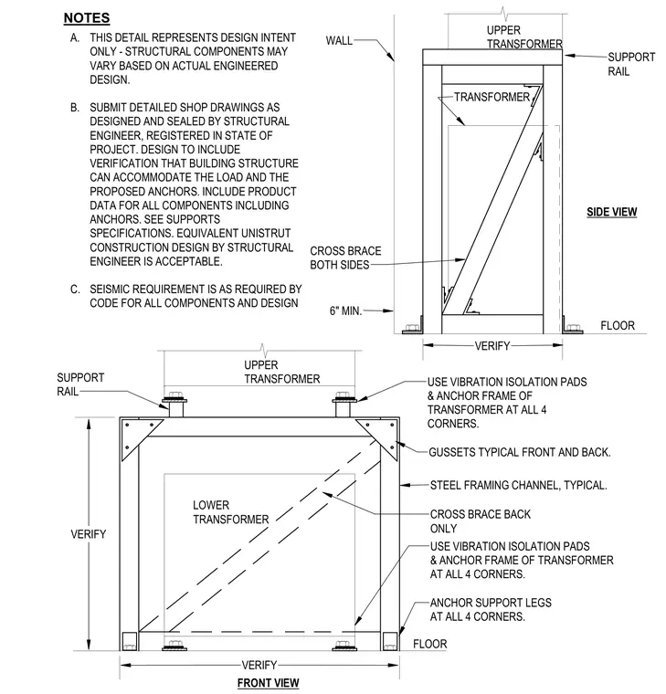
A structural mounting and arrangement for stacked electrical transformers utilizing steel framing channels, such as Unistrut construction. The assembly incorporates support rails, cross bracing on both sides and the back, and typical gusset plates at the frame corners. Vibration isolation pads are positioned beneath the transformer frames at all four corners, with anchor support legs secured to the floor slab. The installation requires structural engineer design verification to accommodate building loads and code-mandated seismic requirements.
FLOOR 6" MIN. SIDE VIEW FRONT VIEW WALL TRANSFORMER FLOOR VERIFY VERIFY VERIFY STEEL FRAMING CHANNEL, TYPICAL. GUSSETS TYPICAL FRONT AND BACK. CROSS BRACE BOTH SIDES NOTES A. THIS DETAIL REPRESENTS DESIGN INTENT ONLY - STRUCTURAL COMPONENTS MAY VARY BASED ON ACTUAL ENGINEERED DESIGN. B. SUBMIT DETAILED SHOP DRAWINGS AS DESIGNED AND SEALED BY STRUCTURAL ENGINEER, REGISTERED IN STATE OF PROJECT. DESIGN TO INCLUDE VERIFICATION THAT BUILDING STRUCTURE CAN ACCOMMODATE THE LOAD AND THE PROPOSED ANCHORS. INCLUDE PRODUCT DATA FOR ALL COMPONENTS INCLUDING ANCHORS. SEE SUPPORTS SPECIFICATIONS. EQUIVALENT UNISTRUT CONSTRUCTION DESIGN BY STRUCTURAL ENGINEER IS ACCEPTABLE. C. SEISMIC REQUIREMENT IS AS REQUIRED BY CODE FOR ALL COMPONENTS AND DESIGN SUPPORT RAIL UPPER TRANSFORMER UPPER TRANSFORMER SUPPORT RAIL LOWER TRANSFORMER USE VIBRATION ISOLATION PADS & ANCHOR FRAME OF TRANSFORMER AT ALL 4 CORNERS. CROSS BRACE BACK ONLY USE VIBRATION ISOLATION PADS & ANCHOR FRAME OF TRANSFORMER AT ALL 4 CORNERS. ANCHOR SUPPORT LEGS AT ALL 4 CORNERS.
Members view this detail in full resolution, download the CAD files (SVG, PDF), and can adapt it in the built-in CAD editor — export DXF, DWG, or PDF.
Start membership