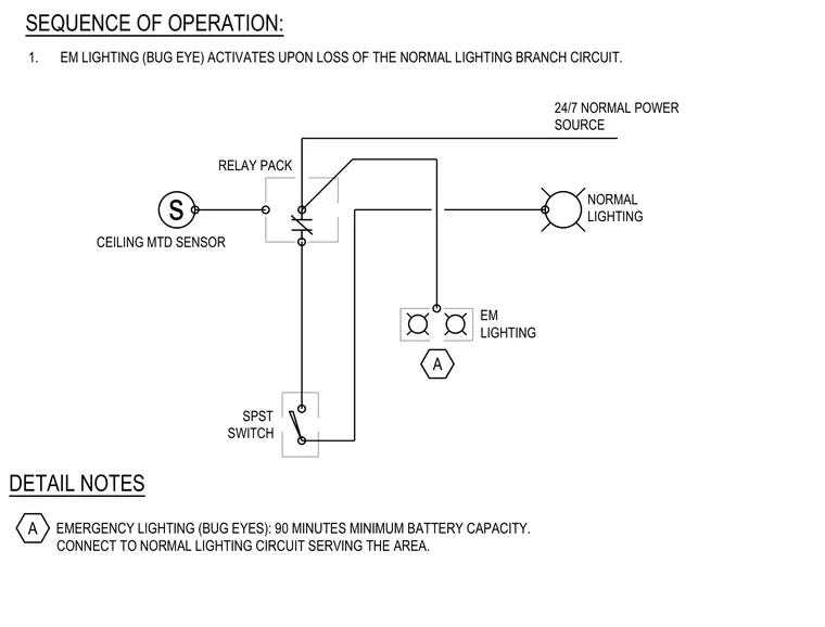
An emergency lighting system diagram incorporates a ceiling-mounted sensor connected through a relay pack to a single-pole single-throw switch and a normal lighting branch circuit. The emergency lighting unit features a 24/7 normal power source and a minimum ninety-minute battery capacity. The emergency lighting activates automatically upon the loss of the normal lighting branch circuit per the sequence of operation notes.
NORMAL LIGHTING SPST SWITCH s 24/7 NORMAL POWER SOURCE DETAIL NOTES EMERGENCY LIGHTING (BUG EYES): 90 MINUTES MINIMUM BATTERY CAPACITY. CONNECT TO NORMAL LIGHTING CIRCUIT SERVING THE AREA. CEILING MTD SENSOR RELAY PACK EM LIGHTING 1. EM LIGHTING (BUG EYE) ACTIVATES UPON LOSS OF THE NORMAL LIGHTING BRANCH CIRCUIT. SEQUENCE OF OPERATION: A A
Members view this detail in full resolution, download the CAD files (SVG, PDF), and can adapt it in the built-in CAD editor — export DXF, DWG, or PDF.
Start membership