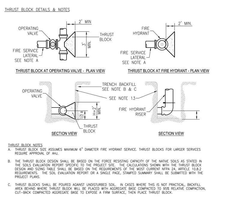
The thrust block is poured directly against undisturbed soil to resist forces generated at fittings and hydrants. The plan and section views show the concrete bearing against the trench wall opposite the fitting, maintaining minimum dimensions such as two feet in length and three feet in width, with a height equal to half the depth plus two feet minimum. Trench backfill is placed around the piping and compacted according to project notes. The assembly accommodates fire service laterals up to six inches in diameter, with larger services requiring approval from the authority having jurisdiction.
THRUST BLOCK AT OPERATING VALVE - PLAN VIEW SECTION VIEW THRUST BLOCK AT FIRE HYDRANT - PLAN VIEW SECTION VIEW
Members view this detail in full resolution, download the CAD files (SVG, PDF), and can adapt it in the built-in CAD editor — export DXF, DWG, or PDF.
Start membership