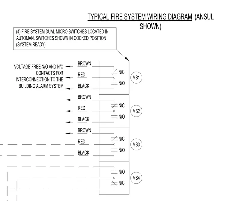
Four fire system dual micro switches are located in the Automan release mechanism and shown in the cocked system ready position. Voltage free normally open and normally closed contacts provide interconnection to the building alarm system. Wire color codings include brown, red, and black leads connected across micro switches MS1 through MS4.
(4) FIRE SYSTEM DUAL MICRO SWITCHES LOCATED IN AUTOMAN. SWITCHES SHOWN IN COCKED POSITION (SYSTEM READY) VOLTAGE FREE N/O AND N/C CONTACTS FOR INTERCONNECTION TO THE BUILDING ALARM SYSTEM TYPICAL FIRE SYSTEM WIRING DIAGRAM (ANSUL SHOWN) N/O N/C MS4 N/O N/C N/O N/C BLACK BROWN RED N/C N/O MS3 MS2 MS1 BLACK BROWN BLACK BROWN RED RED
Members view this detail in full resolution, download the CAD files (SVG, PDF), and can adapt it in the built-in CAD editor — export DXF, DWG, or PDF.
Start membership