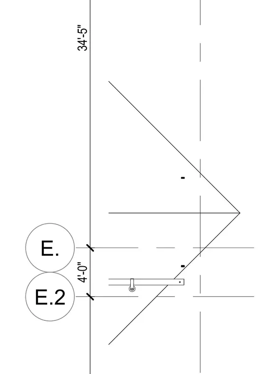
This drawing provides baseline dimensions and vertical elevations for civil engineering layout. A vertical stack of dimension lines indicates key height intervals of thirty-four feet five inches and four feet zero inches. Grid or station reference bubbles marked E and E.2 designate specific alignment points along the referenced axis.
E. E.2 34'-5" 4'-0"
Members view this detail in full resolution, download the CAD files (SVG, PDF), and can adapt it in the built-in CAD editor — export DXF, DWG, or PDF.
Start membership