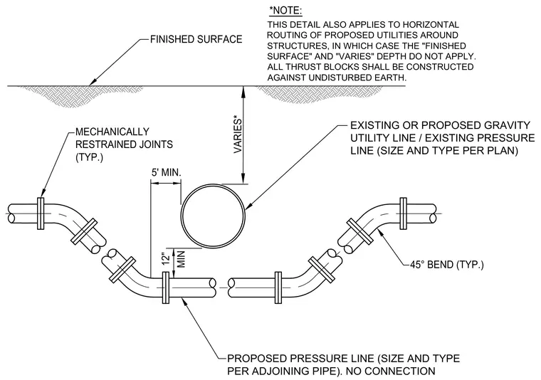
A proposed pressure line routes underneath an existing or proposed gravity utility line or existing pressure line with a minimum vertical clearance of twelve inches and a minimum five-foot horizontal separation from the crossing point. The proposed utility incorporates forty-five degree bends typically on either side of the crossing and utilizes mechanically restrained joints. Thrust blocks must be constructed against undisturbed earth. The drawing also applies to horizontal routing of proposed utilities around structures where the finished surface and varying depth dimensions do not apply.
12" MIN 5' MIN. FINISHED SURFACE 45° BEND (TYP.) PROPOSED PRESSURE LINE (SIZE AND TYPE PER ADJOINING PIPE). NO CONNECTION VARIES* EXISTING OR PROPOSED GRAVITY UTILITY LINE / EXISTING PRESSURE LINE (SIZE AND TYPE PER PLAN) *NOTE: THIS DETAIL ALSO APPLIES TO HORIZONTAL ROUTING OF PROPOSED UTILITIES AROUND STRUCTURES, IN WHICH CASE THE "FINISHED SURFACE" AND "VARIES" DEPTH DO NOT APPLY. ALL THRUST BLOCKS SHALL BE CONSTRUCTED AGAINST UNDISTURBED EARTH. MECHANICALLY RESTRAINED JOINTS (TYP.)
Members view this detail in full resolution, download the CAD files (SVG, PDF), and can adapt it in the built-in CAD editor — export DXF, DWG, or PDF.
Start membership