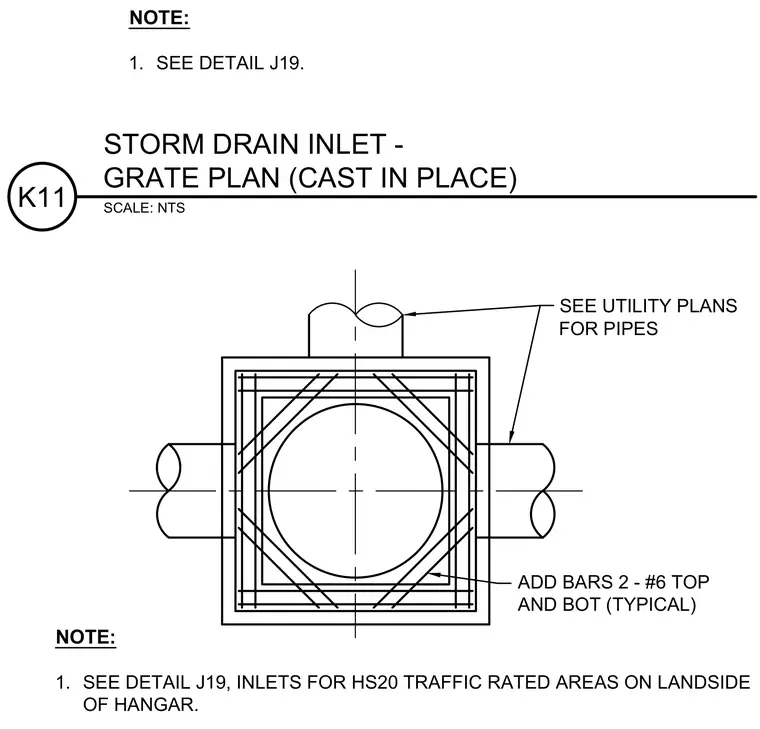
This cast-in-place concrete storm drain inlet plan details the reinforcing bar layout and utility pipe connections. Two number six top and bottom reinforcing bars are placed typically around the perimeter. Utility pipes connect to the inlet sides per the utility plans. Inlets in HS20 traffic-rated areas on the landside of the hangar reference detail J19.
ADD BARS 2 - #6 TOP AND BOT (TYPICAL) SEE UTILITY PLANS FOR PIPES K11 SCALE: NTS STORM DRAIN INLET - GRATE PLAN (CAST IN PLACE) NOTE: 1. SEE DETAIL J19. NOTE: 1. SEE DETAIL J19, INLETS FOR HS20 TRAFFIC RATED AREAS ON LANDSIDE OF HANGAR.
Members view this detail in full resolution, download the CAD files (SVG, PDF), and can adapt it in the built-in CAD editor — export DXF, DWG, or PDF.
Start membership