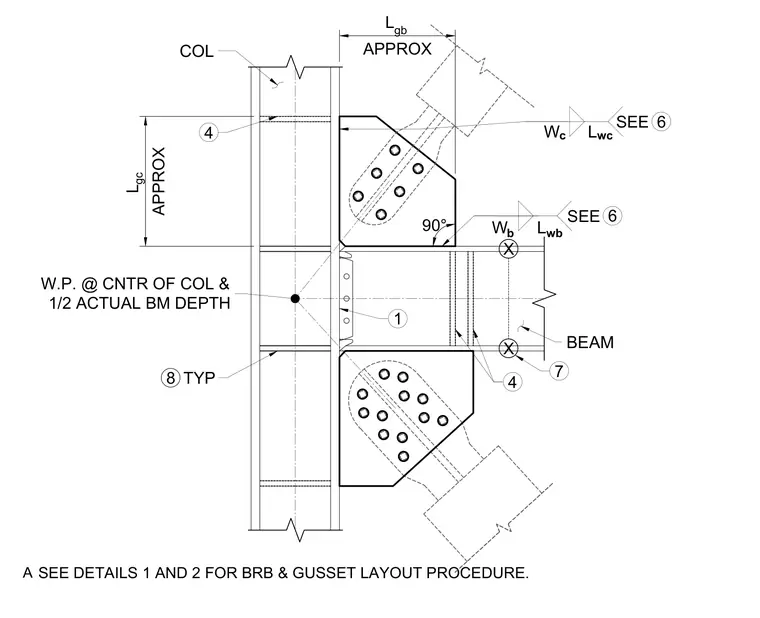
A typical framing connection occurs at the top and bottom of a brace, tying into a vertical steel column and a horizontal steel beam. Gusset plates connect to the diagonal braces using multiple bolts and attach to the structural members with fillet welds. The working point is located at the center of the column and half the actual beam depth. Additional layout procedures for the buckling-restrained brace and gusset are referenced on associated details.
L gc APPROX COL 4 L gb APPROX 4 6 SEE W b BEAM 90° 6 SEE W c 1 W.P. @ CNTR OF COL & 1/2 ACTUAL BM DEPTH X X 7 L wc L wb 8 TYP SEE DETAILS 1 AND 2 FOR BRB & GUSSET LAYOUT PROCEDURE. A
Members view this detail in full resolution, download the CAD files (SVG, PDF), and can adapt it in the built-in CAD editor — export DXF, DWG, or PDF.
Start membership