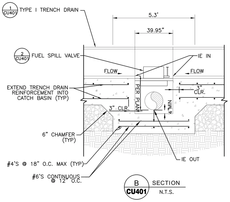
A Type I trench drain incorporates a fuel spill valve and a reinforced concrete trough set into a compacted subgrade. The trench drain assembly includes number four reinforcing bars spaced at eighteen inches on center maximum typically, and number six continuous reinforcing bars spaced at twelve inches on center. The concrete trench features three inches of clear cover typically and a six-inch chamfer typically at the haunches, with a four-inch minimum clearance below the pipe invert. Trench drain reinforcement extends into the catch basin typically. Inverts are indicated for inlet and outlet connections, and dimensions span five point three feet overall with a thirty-nine point nine-five inch internal width.
Members view this detail in full resolution, download the CAD files (SVG, PDF), and can adapt it in the built-in CAD editor — export DXF, DWG, or PDF.
Start membership