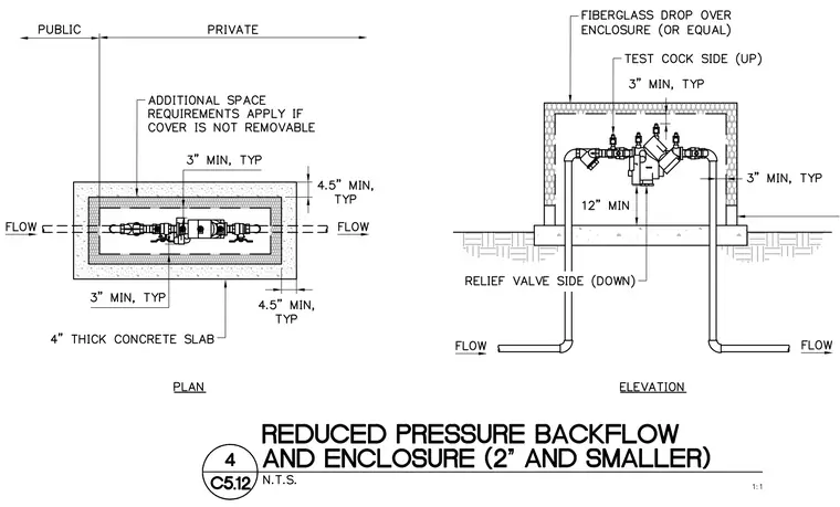
A reduced pressure backflow preventer assembly sized for two inches and smaller is housed within a fiberglass drop-over enclosure or equal. The enclosure sits atop a four-inch thick concrete slab with a typical four and one-half inch clearance from the perimeter. Piping enters and exits through the slab with a minimum twelve-inch clearance to the bottom of the backflow assembly. Typical three-inch minimum clearances are maintained around the piping and backflow device inside the enclosure. Test cocks are positioned on the upper side, and the relief valve is oriented downward. Additional space requirements apply if the enclosure cover is not removable.
Members view this detail in full resolution, download the CAD files (SVG, PDF), and can adapt it in the built-in CAD editor — export DXF, DWG, or PDF.
Start membership