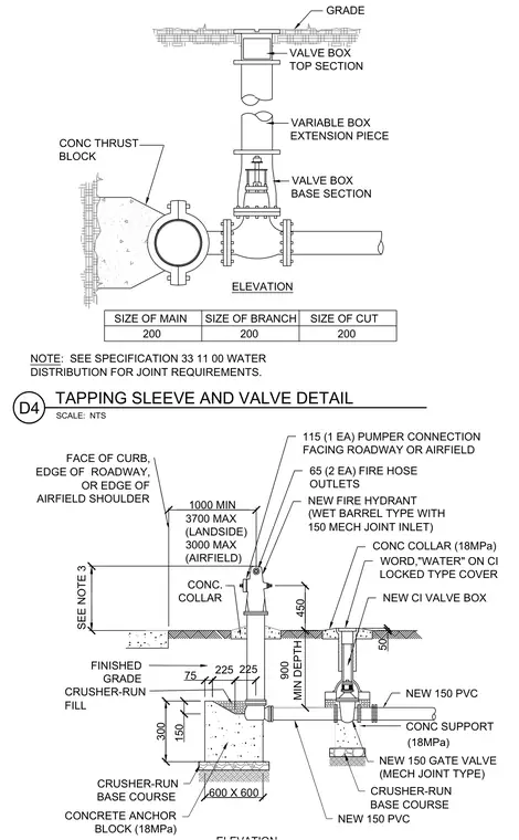
A wet barrel fire hydrant connects to a new polyvinyl chloride water main through a mechanical joint gate valve and tapping sleeve. The assembly features a fire hydrant with one one hundred fifteen millimeter pumper connection facing the roadway or airfield shoulder and two sixty-five millimeter fire hose outlets. The hydrant is supported by an eighteen megapascal concrete anchor block set on a crusher-run base course and surrounded by a concrete collar with a cast iron valve box bearing the word WATER on its locked type cover. A concrete thrust block is placed at the tapping sleeve connection to resist operational forces. Joint requirements adhere to specification thirty-three eleven zero zero for water distribution.
VARIABLE BOX EXTENSION PIECE VALVE BOX TOP SECTION VALVE BOX BASE SECTION GRADE ELEVATION 200 200 200 NOTE: SEE SPECIFICATION 33 11 00 WATER DISTRIBUTION FOR JOINT REQUIREMENTS. SIZE OF MAIN SIZE OF BRANCH SIZE OF CUT NEW 150 PVC CONC SUPPORT CRUSHER-RUN FILL (18MPa) CONC. COLLAR CONCRETE ANCHOR BLOCK (18MPa) NEW 150 PVC FINISHED GRADE 115 (1 EA) PUMPER CONNECTION FACING ROADWAY OR AIRFIELD 65 (2 EA) FIRE HOSE OUTLETS NEW FIRE HYDRANT (WET BARREL TYPE WITH 150 MECH JOINT INLET) CRUSHER-RUN BASE COURSE CRUSHER-RUN BASE COURSE FACE OF CURB, EDGE OF ROADWAY, OR EDGE OF AIRFIELD SHOULDER 3700 MAX (LANDSIDE) 3000 MAX (AIRFIELD) CONC COLLAR (18MPa) WORD,"WATER" ON CI LOCKED TYPE COVER NEW CI VALVE BOX NEW 150 GATE VALVE (MECH JOINT TYPE) CONC THRUST BLOCK TAPPING SLEEVE AND VALVE DETAIL D4 SCALE: NTS 1000 MIN SEE NOTE 3 450 900 MIN DEPTH 50 225 225 75 150 300 600 X 600
Members view this detail in full resolution, download the CAD files (SVG, PDF), and can adapt it in the built-in CAD editor — export DXF, DWG, or PDF.
Start membership