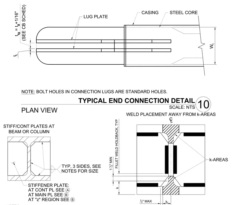
Plan view of a steel core encased by a casing with attached lug plates, along with associated stiffener plate configurations and weld placement restrictions near structural k-areas. The lug plates maintain a designated gap and thickness relative to the gusset plate per the connection schedule, with bolt holes specified as standard holes. Stiffener and continuity plates are detailed at beam or column intersections with typical three-sided welding sizing. Fillet welds maintain a one-and-a-half-inch minimum holdback, positioned away from designated k-areas with specified maximum offsets.
W t t L t tg = t g +1/16" (SEE CB SCHED) STEEL CORE CASING LUG PLATE PLAN VIEW 10 TYPICAL END CONNECTION DETAIL SCALE: NTS NOTE: BOLT HOLES IN CONNECTION LUGS ARE STANDARD HOLES. TYP, 3 SIDES, SEE STIFFENER PLATE: AT CONT PL SEE AT MAIN PL SEE AT "z" REGION SEE A B B NOTES FOR SIZE STIFF/CONT PLATES AT BEAM OR COLUMN k 1 1 2 " MIN FILLET WELD HOLDBACK, TYP WELD PLACEMENT AWAY FROM k-AREAS 12 " MAX k-AREAS CL k 1 h 1 / Z I I o o o
Members view this detail in full resolution, download the CAD files (SVG, PDF), and can adapt it in the built-in CAD editor — export DXF, DWG, or PDF.
Start membership