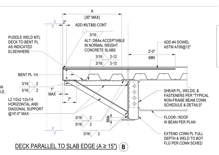
A metal deck runs parallel to the slab edge supported by a one-quarter-inch bent plate, with the metal deck puddle welded to the bent plate as indicated elsewhere. Additional reinforcement includes continuous top and bottom number five bars and an ASTM A706 number four dowel spaced at twelve inches on center. Horizontal and diagonal support utilizes L two-and-a-half by two-and-a-half by one-quarter angles spaced at a maximum of ten feet on center welded with three-sixteenths fillet welds. The supporting wide-flange beam connects via a shear plate with fasteners sized per the typical non-frame beam connection schedule, with the connection plate extended full depth and welded to the bottom flange.
ADD #5(T&B) CONT NOTE: EXTERIOR CURTAIN WALL SYSTEM SHALL NOT IMPOSE A LOAD > 600 PLF ON BEND PL SEE ARCH DRAWING, COORDINATE INSERT W/ CURTAIN WALL MANUFACTURER EXTEND CONN PL FULL DEPTH & WELD TO BOT FLG PER CONN SCHED FLOOR / ROOF W BEAM PER PLAN SHEAR PL, WELDS, & FASTENERS PER "TYPICAL NON-FRAME BEAM CONN SCHEDULE & DETAILS" ADD #4 DOWEL ASTM A706@12" ANGLE BRACE, ALIGN W/ EDGE STIFF ANGLE, PUDDLE WELD MTL DECK TO BENT PL AS INDICATED ELSEWHERE L2 1/2x2 1/2x1/4 HORIZONTAL AND DIAGONAL SUPPORT @10'-0" MAX BENT PL 1/4 DECK PARALLEL TO SLAB EDGE (A ≥15") MIN 2'-0" (30" MAX) A 2" MAX 1" 7" BMk 3/16 2 3/16 2 3/16 2 3/16 2 3/16 2 3/16 2-12 3/16 2-12 3/16 B ALT: DBAs ACCEPTABLE IN NORMAL WEIGHT CONCRETE SLABS
Members view this detail in full resolution, download the CAD files (SVG, PDF), and can adapt it in the built-in CAD editor — export DXF, DWG, or PDF.
Start membership