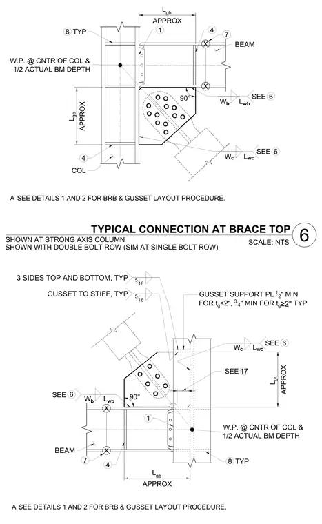
A typical brace top connection at a strong axis steel column features a gusset plate welded to a gusset support plate and bolted to a buckling-restrained brace. The assembly includes a beam connected to the column flange with a bolted shear tab and supported by a gusset support plate of half-inch minimum thickness for gusset thicknesses under two inches, and three-quarter-inch minimum for thicker plates. Five-sixteenth-inch fillet welds secure the gusset to stiffeners along three sides top and bottom typically. Work points are located at the center of the column and half the actual beam depth.
COL 4 L gb APPROX 6 SEE BEAM 90° L gc APPROX 6 SEE W c W b W.P. @ CNTR OF COL & 1/2 ACTUAL BM DEPTH X X 1 4 7 L wc L wb 8 TYP TYPICAL CONNECTION AT BRACE TOP SCALE: NTS SHOWN AT STRONG AXIS COLUMN SEE DETAILS 1 AND 2 FOR BRB & GUSSET LAYOUT PROCEDURE. A SHOWN WITH DOUBLE BOLT ROW (SIM AT SINGLE BOLT ROW) 90° W b 6 SEE L gb APPROX BEAM L gc APPROX W.P. @ CNTR OF COL & 1/2 ACTUAL BM DEPTH 4 X X 7 8 TYP GUSSET TO STIFF, TYP 6 SEE 3 SIDES TOP AND BOTTOM, TYP 516 516 W c L wb L wc GUSSET SUPPORT PL 12 " MIN FOR t g <2", 3 4 " MIN FOR t g ≥2" TYP 1 SEE DETAILS 1 AND 2 FOR BRB & GUSSET LAYOUT PROCEDURE. A 17 SEE 6
Members view this detail in full resolution, download the CAD files (SVG, PDF), and can adapt it in the built-in CAD editor — export DXF, DWG, or PDF.
Start membership